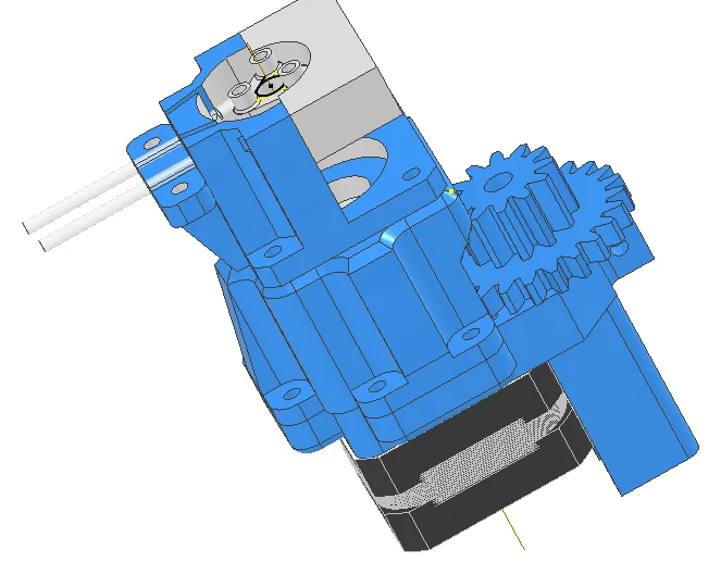
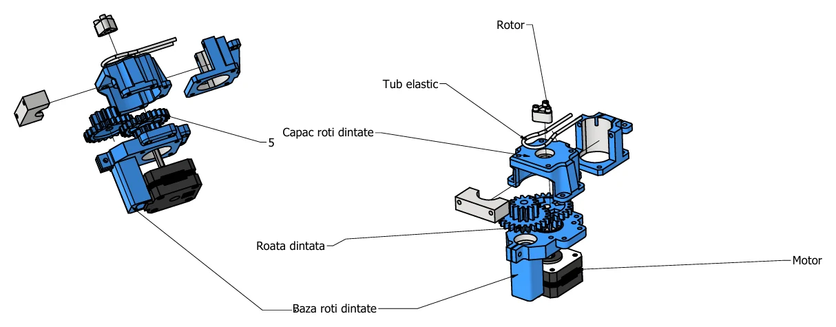
The custom three-roller pump, its first-order displacement model and the strict distinction between motor command resolution and delivered-volume accuracy.
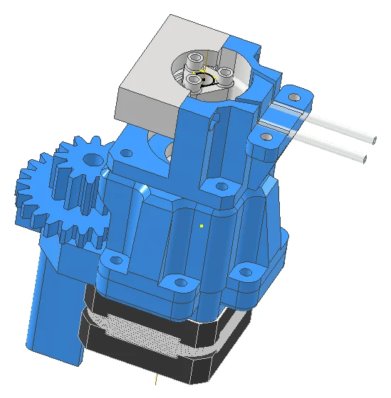
Explanation
A three-roller rotor compresses a flexible tube. Advancing the compression moves liquid while the liquid remains inside the replaceable tube. The motor provides a precise command, but only calibration determines the volume that actually exits the tube.
Documented design
| Parameter | v2 design value | Classification |
|---|---|---|
| Pump type | three-roller peristaltic | design architecture |
| Tube | 3.2 mm ID / 6.4 mm OD silicone | design specification |
| Nominal channel radius | 18 mm | CAD specification |
| Drive | NEMA 17, 1.8° full step, direct drive | component specification |
| Command mode | 1/16 microstepping | firmware design |
| Housing | PETG prototype geometry | CAD specification |
| System channels | four independent pump modules | system design |
First-order model
ExplanationTube area is calculated from its internal diameter.
ExplanationIdeal volume per turn is tube area multiplied by the effective squeezed length and the number of displacement events.
With di = 3.2 mm, Leff = 25 mm and Ne = 3, the report model gives At ≈ 8.04 mm² and Vrev,ideal ≈ 0.603 mL/rev.
ExplanationThe ideal volume is corrected by an efficiency measured on the real pump.
ExplanationFlow equals delivered volume per turn multiplied by turns per minute.
Motor-command increment
ExplanationMotor step angle and microstepping determine how many commands produce one rotor revolution.
ExplanationNominal volume per command is the measured volume per revolution divided by commands per revolution.
Why calibration is mandatory
Tube recovery, occlusion, viscosity, suction head, outlet pressure, roller geometry, motor torque, microstep non-linearity and tube wear all alter delivered volume. Peristaltic-pump modelling and published multi-channel systems therefore use physical calibration rather than geometry alone.
Progress classification
The pump geometry and four-channel module are substantial v2 engineering progress. The supplied report documents CAD, component selection and the analytical model. No traceable FlavoRotor gravimetric dataset accompanies the report, so delivered-volume performance remains unclaimed until CR-PMP-001 is published.
FlavoRotor design provenance
The system-specific configuration on this page is traced to the supplied FlavoRotor engineering records.
CAD documentation