
Transmission ratio, overload behaviour, preliminary calculations and the required slip-torque validation.
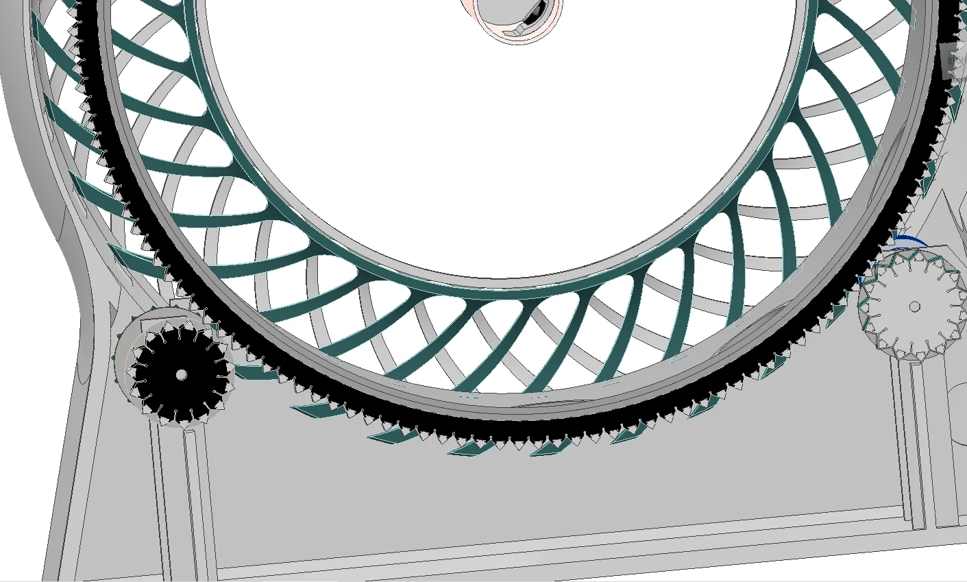
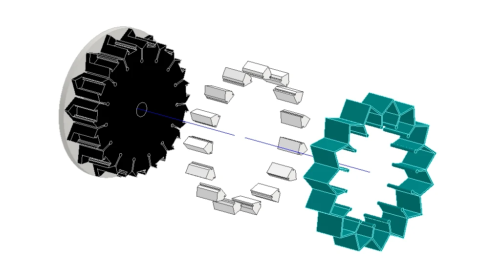
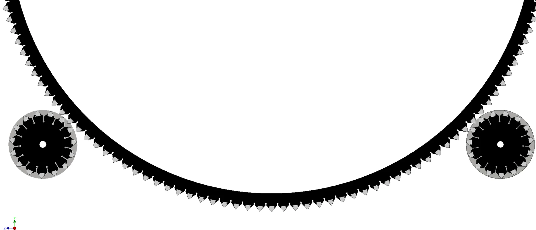
Design definition
| Parameter | Design record |
|---|---|
| Driving wheel teeth | 15 |
| Driven wheel teeth | 146 |
| Nominal ratio | 146/15 = 9.733:1 |
| Magnet type | NdFeB N42, Ø8 × 3 mm in the v2 specification |
| Nominal air gap | 2.5 mm in the v2 specification |
| Intended behaviour | non-contact torque transfer with overload slip |
Kinematic model
ExplanationThe ratio between driven and driving teeth defines how much the drive reduces speed and increases available torque.
ExplanationDriven speed is motor speed divided by the transmission ratio.
ExplanationDividing 60 by the driven speed gives the duration of one output rotation.
Why the earlier force estimate is not a final result
A magnetic dipole approximation can support preliminary sizing, but the short separation, finite cylindrical magnets, alternating polarities, tooth geometry and simultaneous interactions violate the simplest far-field assumptions. The resulting torque must therefore be treated as an analytical estimate, not a verified 3.9 N·m capability.
Required validation
| Test | Method | Reported output |
|---|---|---|
| Static slip torque | force gauge at known radius | torque-angle curve and peak slip torque |
| Starting load | incremental drum load | minimum starting torque and motor current |
| Speed stability | encoder or video tachometry | mean RPM, SD and periodic ripple |
| Endurance | loaded operation over defined hours | slip events, temperature and drift |
| Misalignment | controlled axial/radial offset | torque margin and failure threshold |
ExplanationMeasured slip torque is compared with the largest required torque. A value above one leaves a positive operating margin.
FlavoRotor design provenance
The system-specific configuration on this page is traced to the supplied FlavoRotor engineering records.